"AE801" / Technical Information
Principle of operation
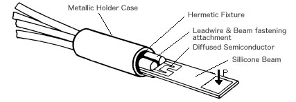
The transducer-element has two resisters, one on each side of the beam. When the tip of the beam is deflected, the zones into which these resister are diffused will be stressed, and thus the resister will change their values, that is the resister in the compressed zone will decrease its value and vice versa. The change in resistance is determined by various parameters such as deflection, beam dimensions, and doping level of the resister.
Measurement Range
Amount of Load (P) / Deflection (δ) can be calculated through the following formula up to the range of maximum strain (εmax = 1000 μstrain) of the silicone beam. Practically speaking, however, it is recommended that this formula is used within the range of the Maximum Load (Pmax) / Maximum Deflection (δmax) as the official measuring range.
δ=P*L^3/E*I=(2/3)*εmax*L^2/h
E : Modulus of elasticity for silicon
I : Moment of inertia of beam
εmax : Max strain in the beam
L : Distance from fixed end
Measurement range (when load increased on the tip of a beam)
Pmax : 12 gr (118 mN approx.)
δmax : 0.1 mm
*The output value that can be got through the Wheatstone Bridge at Pmax / δmax is 25 mV/V approx.
Instrumentation
A direct reading can be made on an oscilloscope or by digital voltmeter as the AE801/Element can afford the output of 25 mV/V approx. in case when it is provided through the Wheatstone Bridge. However, if you want to get an output in the level of "v", an amplification by means of the AMP may be required. Refer to simple amplifier circuits we are giving below. Our Model 5693 DC Strain AMP can also be used for the same purposes.
Refer to basic amplifier circuit (* Forgive us from receiving any questions on these amplifier circuits.)
[Example - 1]
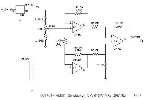
We are showing in Fig.1 below the simplest method where an instrumentation AMP circuit is used. A bridge circuit is composed in this circuit with the the AE801 and fixed resistors to which an input voltage of 5V is applied. Its output is received on an instrumentation AMP composed with an Operation AMP of the Industrial Standard.
[Example - 2]
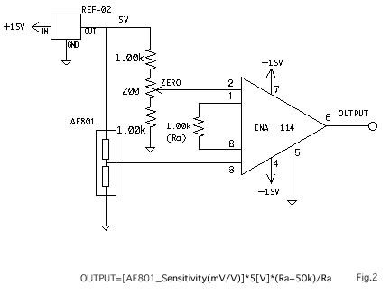
The circuit in Fig.2 is that in which the circuit per Fig.1 is replaced with an instrumentation circuit made by Burr Brown Company. At present, instrumentation AMP IC are offered from Analog Devices Co., Linear Technologies Co., and so on, and any of which may also be used in your circuits.
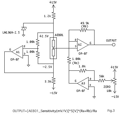
[Example - 3]
In the circuit shown in Fig.3, a voltage of the same absolute value but in plus and minus is applied to the AE801 and its output is amplified by the A2 OP-AMP. The A1 generates a negative voltage for the sensor and the A3 produces a zero point adjustment voltage for the A2 OP-AMP.